Small joint cavity, high vibration and high ripple: DC-Link capacitor selection for 12S~16S UAV
During the testing of joint-drive prototypes for 12S–16S drones, issues such as excessive DC-link ripple and high capacitor surface temperatures may arise. Addressing these often requires board redesigns, component replacements, and rescheduled flight tests—all of which delay project milestones. In many cases, capacitors that meet nominal capacitance and voltage ratings still experience overheating or reliability failures under actual operating conditions. Meeting nominal specifications does not guarantee suitability for specific joint-drive applications; component selection must be verified against actual ripple frequency, peak DC-link voltage (including regenerative voltage spikes), internal enclosure temperature, and vibration profiles.
In applications such as gimbal joints, robotic arm joints, electric actuators, and joint servo drives, BLDC (brushless DC) or PMSM (permanent magnet synchronous) motors are driven by high-frequency PWM signals. The DC-link capacitors must absorb bus ripple and handle energy fed back during regenerative braking. The operating environment presents several challenges:
First, space constraints: Joint housings are often cramped with poor airflow, frequently forcing capacitors to be mounted horizontally, which inherently limits heat dissipation.
Second, vibration: Throughout their service life, components are subjected to continuous wide-band vibration and the mechanical shocks of takeoff and landing, placing long-term stress on leads, solder joints, and seals.
Third, harsh environmental conditions: Factors such as high altitude, condensation, humidity, and salt spray erode safety margins for both thermal management and electrical insulation. Furthermore, the demand for lightweight designs necessitates high capacitance within a very small volume.
Compounding these challenges is the trend toward standardized battery configurations (12S, 14S, and 16S), where a single joint design must accommodate multiple DC-link voltage levels. Any oversight during the component selection phase typically leads to a cluster of failures during the prototype or small-batch production stages.
The consequences of such failures extend far beyond simply replacing a capacitor. They often necessitate thermal design overhauls, testing delays, and increased development costs. Excessive heat accelerates component degradation, while failures in leads, solder joints, or seals can lead to a loss of control over the joint—potentially causing an in-flight shutdown. Moreover, the costs associated with after-sales repairs and the re-validation of replacement components are significant. Given that drones are aircraft, a loss of control in a joint directly compromises flight safety and damages brand reputation. Matching Only Capacitance and Voltage Rating Is Insufficient: Three Additional Verification Criteria for Robotic Joint Applications
When selecting general-purpose axial or radial aluminum electrolytic capacitors—or their imported counterparts—relying solely on capacitance and voltage ratings is inadequate. Without proper derating and structural validation based on actual ripple frequency, peak DC-bus voltage (including regenerative braking spikes), internal enclosure temperature, and vibration profiles, components with similar nominal specifications may still suffer from insufficient thermal lifespan or poor mechanical reliability when subjected to the demanding conditions of a robotic joint. Before implementing any replacement, comprehensive validation at both the PCB and system levels is essential. Furthermore, factors such as lead times and responsiveness to design changes for imported components should be evaluated early in the project. (This article does not offer conclusions regarding the relative merits of specific brands.)
From an electrical perspective, ripple current generates Joule heating via the Equivalent Series Resistance (ESR), accelerating electrolyte loss and the degradation of electrical parameters. The DC-bus voltage is compounded by PWM-induced ripple, cable inductance, and voltage spikes from regenerative braking; insufficient voltage margin directly compromises reliability. Additionally, axial leads and longer circuit loops increase the Equivalent Series Inductance (ESL). Therefore, capacitance alone is not a sufficient metric.
From a mechanical and thermal standpoint, continuous vibration causes repeated flexing of axial leads, which can lead to cracked solder joints, lead fatigue, and compromised sealing. Limited space for heat dissipation within the enclosure, combined with the capacitor’s own self-heating, significantly shortens its operational lifespan. Harsh environmental factors—such as high altitude, condensation, humidity, and salt spray—further exacerbate these issues.
Even if nominal specifications appear similar, a component may still fail to meet thermal or mechanical reliability requirements under the specific operating conditions of a robotic joint. While domestic alternatives are available, they cannot be selected simply by comparing datasheets; rigorous validation at both the PCB and system levels is mandatory.
Yongming’s Solution:
Three Voltage Tiers, Tailored to Specific Operating Conditions
Yongming’s LKE and LKM series of axial aluminum electrolytic capacitors are available in three voltage ratings—63V, 80V, and 100V—covering 12S to 16S battery system platforms. The approach is not to use a "one-size-fits-all" part number, but rather to make selections based on specific requirements: maximum bus voltage, capacitance, dimensions, actual ripple current, and service life. Selecting components this way ensures the right choice from the start, preventing the need for thermal design rework—or delays in flight testing—that might otherwise arise from miscalculating voltage ratings or ripple currents.
How to determine the voltage rating: First, consider the system platform; then, account for voltage spikes.
| Platform | Full Charge Voltage (Approx.) | Recommendation |
| 12S | 50.4V | 63V meets the lower limit. Adoption is subject to regenerative peak review and prototype verification; 80V offers higher voltage margin, select based on size / cost |
| 14S | 58.8V | 80V meets the lower limit; 100V provides higher margin, select based on size / cost and regenerative peak review |
| 16S | 67.2V | 100V meets the lower limit. Regenerative braking peak review is still required |
A general rule of thumb: first, determine the lower limit of the rated voltage by taking the maximum bus voltage and dividing it by 0.8; then, verify this against the peak voltage generated during regenerative braking. The safety margin must be balanced against factors such as physical size, capacitance, and cost.
Configurations like 12S, 14S, and 16S can share a common structural platform for the joints, reducing redundant structural development. Capacitors should be selected and validated for each voltage tier within the platform; this avoids the inefficiency of having a unique part number for every single platform configuration, while also preventing additional rounds of thermal design rework and delays in flight testing.
Key parameters: ESR (Equivalent Series Resistance) and rated ripple current.
| Series | Specification | Dimension (mm) | ESR (Ω) | Ripple Current (mA) |
| LKM | 63V 470μF | 12.5×16 | 0.05 | 2100 |
| LKM | 63V 680μF | 12.5×20 | 0.0485 | 2410 |
| LKM | 80V 330μF | 12.5×16 | 0.094 | 1368 |
| LKM | 80V 560μF | 12.5×25 | 0.048 | 2110 |
| LKM | 100V 100μF | 10×14 | 0.14 | 1040 |
| LKM | 100V 330μF | 12.5×25 | 0.047 | 2140 |
| LKE | 80V 270μF | 10×20 | 0.06 | 1560 |
| LKE | 80V 470μF | 12.5×20 | 0.04 | 1950 |
| LKE | 100V 470μF | 12.5×27 | 0.045 | 2250 |
| LKE | 100V 330μF | 14.5×16 | 0.047 | 1650 |
The test conditions for ESR and rated ripple current in the table are 105°C and 100 kHz; data sourced from the Yongming LKE/LKM datasheet.
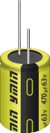
Fig. 1 LKM 63V 470μF 12.5×16
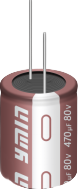
Figure 2: LKE 80V 470μF 12.5×20
For standard axial aluminum electrolytic capacitors of the same specifications, the typical ESR generally falls within the 0.12–0.2Ω range (industry standard). The LKE and LKM series, however, achieve values in the 0.04–0.09Ω range—a significant reduction compared to the industry norm. A lower ESR helps suppress heat generation caused by ripple current.
Low ESR and high ripple-current capacity directly address two critical challenges in joint-actuator operating conditions: heat generated by ripple current flowing through the ESR, and voltage margin during regenerative braking spikes. For example, the LKE 80V 470μF capacitor features an ESR of 0.04Ω and a ripple-current rating of 1950mA, while the LKM 80V 560μF model offers an ESR of 0.048Ω and a ripple-current rating of 2110mA.
When selecting components, calculate the temperature rise based on actual ripple current and frequency—do not rely solely on nominal values specified at room temperature. Lowering the temperature rise slows down electrolyte loss and parameter degradation, thereby extending service life and reducing the risk of field failures. For a project, this can prevent the need for costly PCB redesigns and additional rounds of testing caused by excessive temperature rise.
Three-Step Selection Process: Determine Voltage Rating, Calculate Temperature Rise, and Manage Vibration
Step 1: Determine the voltage rating. First, establish the minimum rated voltage by calculating "maximum bus voltage ÷ 0.8." Then, verify this against regenerative braking spikes: for 12S systems, consider 63V/80V; for 14S systems, look at 80V/100V; and for 16S systems, use 100V.
Step 2: Calculate temperature rise. Select a component with low ESR and high ripple-current capacity based on the actual ripple current and frequency, then calculate the expected temperature rise. Estimate the service life by accounting for the maximum operating temperature, ripple current, and the component's rated lifespan—do not simply rely on nominal values at room temperature.
Step 3: Manage vibration. Employ a low-profile, horizontal mounting configuration to shorten busbar loops, thereby reducing equivalent series inductance (ESL). Mitigate vibration-induced stress through methods such as mechanical clamping, adhesive bonding, potting, or strain relief. Conduct full-system validation based on actual vibration profiles, specifically inspecting component leads, solder joints, and the integrity of seals.
A rigorous three-step component selection process pays dividends by reducing the need for post-sales repairs and replacement verifications. Furthermore, utilizing domestically sourced components—supported by batch traceability and change notification protocols—helps to minimize the risk of supply disruptions.
Summary
Selecting DC-link capacitors for power electronics requires a comprehensive evaluation covering voltage ratings, ripple-induced temperature rise, and vibration resistance. For 12S/14S/16S systems, the minimum voltage rating should be determined by dividing the maximum DC-link voltage by 0.8, with further verification against voltage spikes caused by regenerative braking. Ripple current and temperature rise must be calculated based on actual operating frequencies and current levels. Vibration resistance should be validated at the system level using relevant vibration profiles, with careful inspection of leads, solder joints, and seal integrity. Completing these checks helps minimize the need for thermal design rework, testing delays, and post-sales repairs. Ultimately, the true value—beyond the unit purchase price—is reflected in actual project data regarding temperature rise, ripple performance, service life, and maintenance costs.
Yongming’s LKE and LKM series (63V/80V/100V) axial electrolytic capacitors can be precisely matched to your requirements—including DC-link voltage, ripple current, capacitance, thermal conditions, and vibration resistance—helping to identify potential mismatches between voltage ratings and mechanical mounting structures during the selection phase. Please refer to the official datasheets for technical specifications, and confirm specific part numbers based on the results of prototype validation.
Need datasheets, a selection checklist, or support with prototype validation for the LKE/LKM series? Contact the Yongming technical team; we will provide you with our selection methodology and validation checklist.